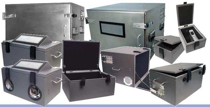
Radio frequency (RF) shielded test enclosures, also known as Faraday cages, provide a conductive space that blocks electromagnetic interference (EMI) for electronics testing and certification. Correctly designed RF shielded enclosures are critical infrastructure for the electronics industry to accurately and reliably perform electromagnetic compatibility (EMC) testing on electronic devices and equipment.
History of RF Shielding
The concept of electromagnetic shielding dates back to the late 18th century experiments of physicist Michael Faraday. Faraday discovered that a conducting material could block exterior static electric fields if it formed a continuous closed surface. This discovery led to the development of metallic screen cages that became known as Faraday cages.
In the early 20th century, radio technology emerged and the need arose to shield electronics from external RF interference and contain emissions. RF Shielded Test Enclosures rooms were constructed using thick metal walls, doors, seams and conductive gaskets. Over time, the demand grew for more portable yet still highly shielded enclosures that could be used on test ranges and in labs. This prompted innovations in lightweight yet robust enclosure designs.
EMC Testing Requirements
All electronic products sold globally must pass EMC regulatory testing to demonstrate compliance with electromagnetic emissions and immunity standards. This protects equipment function and prevents interference with other devices. Standards such as FCC, CE, IC, KC mark, and others specify the test methods, limits and facilities that are required.
Critical components of an accredited EMC lab include an RF anechoic chamber and shielded enclosure. The enclosure provides a controlled space to inject interference signals into a device under test (DUT) or measure its emissions. For accurate, repeatable results, the enclosure must achieve high shielding effectiveness across wide frequency ranges up to 10GHz and beyond.
Key Factors in Enclosure Design
Material – High conductivity aluminum or copper is typically used for the walls/doors as these metals can attain shielding in excess of 100dB. Thick panels provide greater protection at lower frequencies.
Seams – All joining surfaces between panels must be overlapped or formed into continuous conductive seams, often using compressive gaskets, to maintain continuity.
Control/Observation Ports – Windows or feedthrough holes for cables are fitted with conductive gaskets or filtering to prevent gaps.
Grounding – The enclosure is connected to a low impedance earth ground to remove charge buildup and ensure a zero voltage potential inside.
Suppression Filters – Ventilation and any data/power feeds pass through filters to block RF ingress/egress at the portals.
Internal Absorbers – RF absorber pyramids or cones damp reflections inside and help achieve an anechoic environment.
Modern Enclosure Designs
Advances in materials and construction have resulted in significantly lighter and more portable shielded enclosures while maintaining strict shielding integrity. Tripod or rolling cart designs allow them to be easily moved yet provide robust structures.
Fully embedded conductive gasketing in the seams of multilayer composite panels is a leading construction technique. New absorber technologies such as carbon loaded foams deliver anechoic performance in smaller packages as well. Some modern designs even integrate shielded test instrumentation inside the enclosure on internal frames or benches.
Semi-anechoic enclosures offer a cost-effective option versus a full shielded room where the reflected signals are less critical for a given test. These have RF absorber material covering three internal walls and the top but maintain a hard back wall. Optional upgrades include emission measurement antennas, cooling fans and automated control systems.
Industry Standards and Certification
Manufacturers of RF shielded enclosures self-certify their products to attenuation specifications which are traceable to rigorous industrystandardized test methods like MIL-STD-285, IEC/EN 61000-4-3 or other recognized procedures. Independent testing laboratories also offer certification services through standardized and customized testing protocols.
Certification gives users assurance that the published shielding data is accurate and the enclosure will perform reliably for its intended purpose. It also maintains the accreditation of any EMC lab using the enclosure. Regular maintenance and requalification testing ensures the enclosure continues meeting specifications over its lifespan.
Key Applications
Mobile device – Wireless smartphones, tablets, Wi-Fi hotspots, Bluetooth devices.
Automotive – Components for vehicle electronics, infotainment, advanced driver assist systems.
Medical – Pacemakers, defibrillators and other implantables, imaging equipment, surgical tools.
Avionics – Onboard systems for aircraft, satellites, drones.
Wireless infrastructure – 5G radios and nodes, small cells, macro base stations.
Industrial – Motor drives, PLCs, frequency converters, sensor networks.
Proper RF shielding is essential for achieving valid, repeatable EMC test data to satisfy evolving regulations. High performance shielded enclosures are indispensable tools that have enabled major technological advancement. Continued materials research and design innovation aim to provide even more capabilities in smaller, lighter and lower cost packages to support global connectivity and the Internet of things.
*Note:
1. Source: Coherent Market Insights, Public sources, Desk research
2. We have leveraged AI tools to mine information and compile it

